Board to Board Connector Pin Assignment
List of Interfaces / PWR needed between boards: (Pin Budget)
| # | Signal Group | Count | Total Pins |
|---|---|---|---|
| 1 | +3V3 | 2× | 2 |
| 2 | +5V | 2× | 2 |
| 3 | +12V (Note below) | 6× | 6 |
| 4 | GND - +12V Return Path | 6× | 6 |
| 5 | PWM | 2× | 2 |
| 6 | Gate Driver SPI | 2× | 8 |
| 7 | ESC MCU UART | 2× | 4 |
| 8 | Gate Driver EN | 2× | 2 |
| 9 | Gate Driver nFault INT | 2× | 2 |
| 10 | ESC Temp Sensor I2C | 2× | 4 |
| 11 | Cell Voltages | 6x | 6 |
| 12 | Fuel Gauge I2C | 1× | 2 |
| 13 | Cell Monitoring I2C | 1× | 2 |
| 14 | Camera UART | 1× | 2 |
| 15 | Dynamixel TTL | 1× | 1 |
| 15 | Alternating GND | ~15x | 15 |
| TOTAL | 66 |
Important Note: For +12V, Total Max Dynamixels Current at stall torque is 4.6A. Each pin in B to B connector can do 1A Max, so using 6 pins in parallel. Importantly, +12V needs to have GND very close to it for return path (Current takes the path of least resistance) or else the return current will flow through all the other GND Pins which will result in overlap of return paths of Digital / Analog signals and Noisy PWR leading to noise coupling. (Very bad from SI/PI prespective)
Choosen Connector:
Plug:
STWXE BB51-84AT-1-3HB 84 Pin Mezzanine Connector Plug
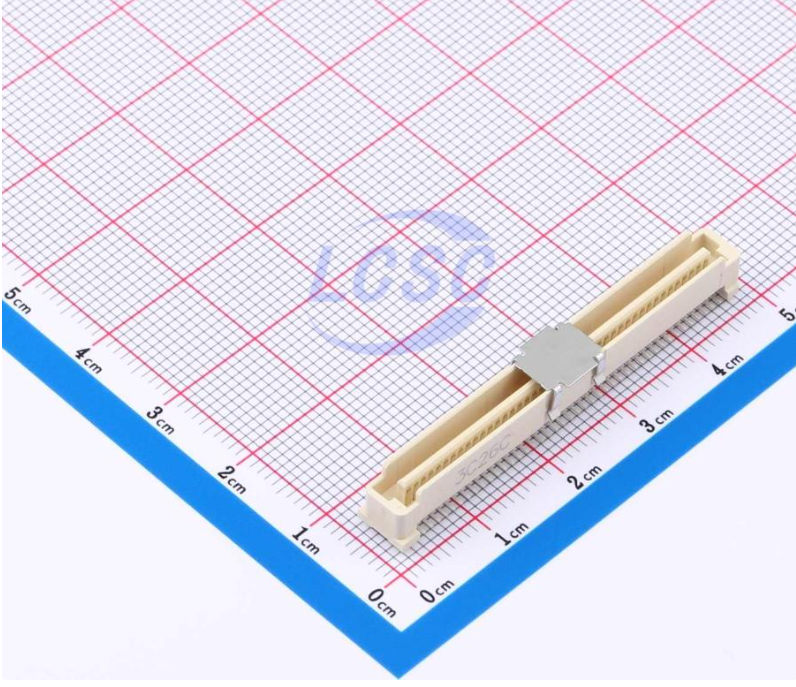
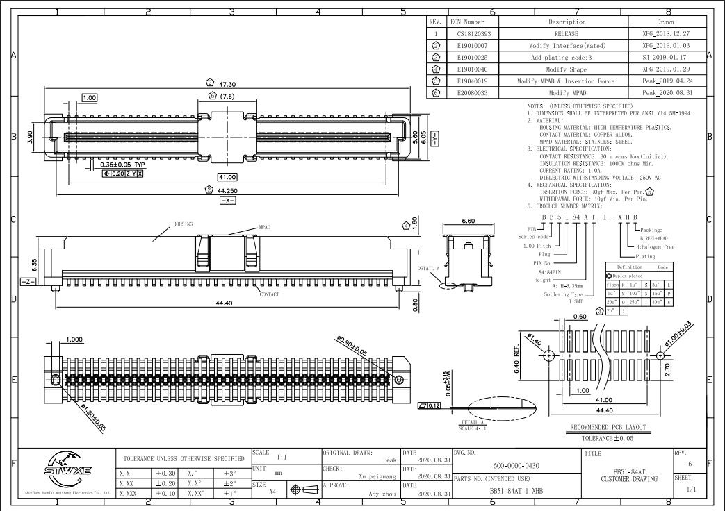
Socket:
STWXE BB52-84AT-1-3HB 84 Pin Mezzanine Connector Socket
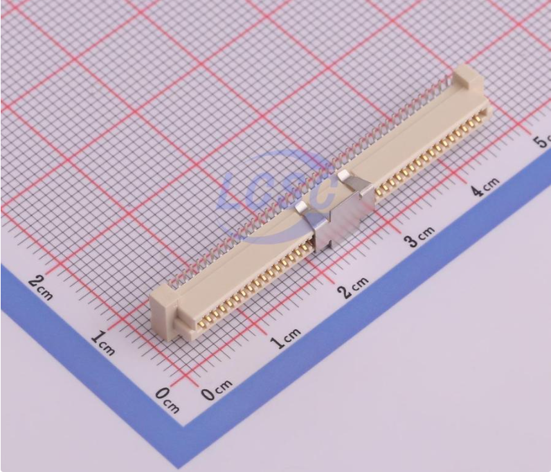
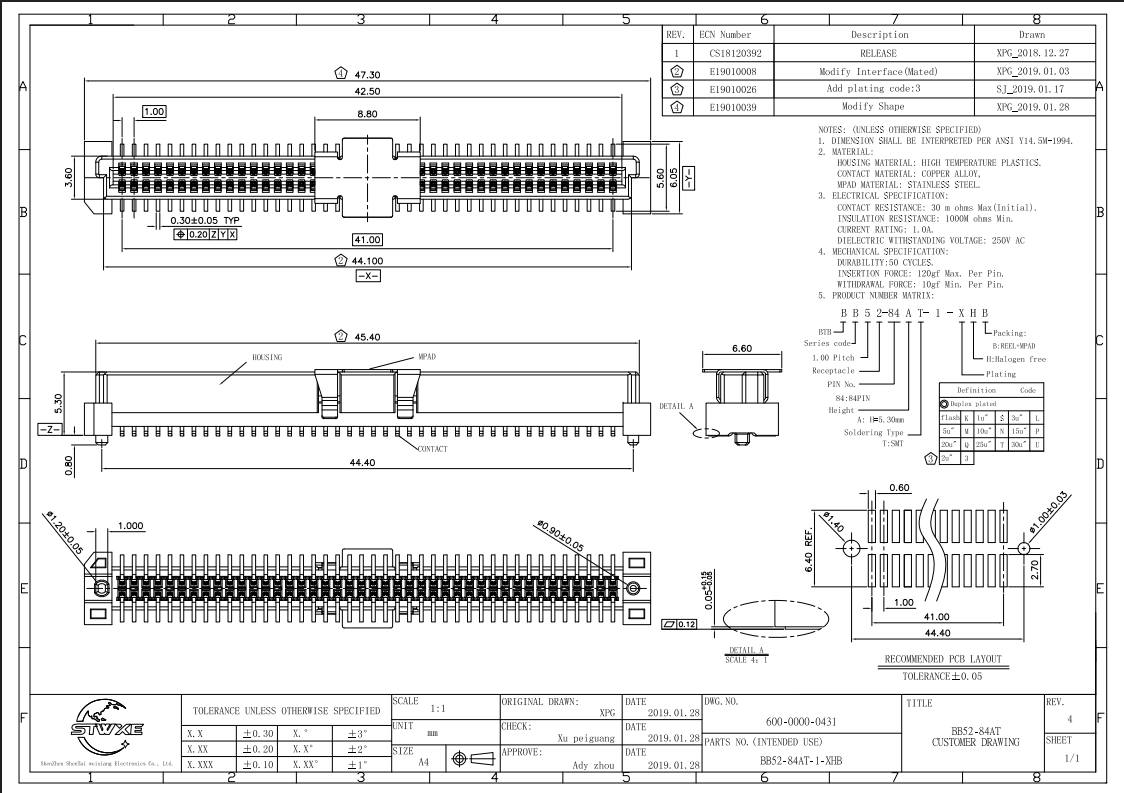
Specifications:
- 84 Pins
- 1mm Pitch
- 1A Max per Pin
- Keyed
- Mating Height: 6.35mm
- Contact Material: Copper Alloy
- Durability: 50 Cycles (Note Below)
Note on durabilty: 50 Cycles is very low so we need to prevent pluging and unplugging as much as possible. Keep it mated and assembled as much as possible.
Pin Assignment:
| Net | Pin | Pin | Net | |
|---|---|---|---|---|
| V_CELL6 | 1 | 2 | +3V3 | |
| V_CELL5 | 3 | 4 | GND | |
| GND | 5 | 6 | +5V | |
| V_CELL4 | 7 | 8 | GND | |
| V_CELL3 | 9 | 10 | ESC Temp Sensor I2C_SDA | |
| GND | 11 | 12 | ESC Temp Sensor I2C_SCL | |
| V_CELL2 | 13 | 14 | GND | |
| V_CELL1 | 15 | 16 | Cell Monitoring I2C_SDA | |
| GND | 17 | 18 | Cell Monitoring I2C_SCL | |
| PWM1 | 19 | 20 | GND | |
| GND | 21 | 22 | Gate Driver_1 EN | |
| PWM2 | 23 | 24 | Gate Driver_2 EN | |
| GND | 25 | 26 | +3V3 | |
| Fuel Gauge I2C_SDA | 27 | 28 | GND | |
| Fuel Gauge I2C_SCL | 29 | 30 | +5v | |
| GND | 31 | 32 | GND | |
| Gate Driver_1 SPI_CS | 33 | 34 | Gate Driver_1 nFault INT | |
| Gate Driver_1 SPI_SCLK | 35 | 36 | Gate Driver_2 nFault INT | |
| GND | 37 | 38 | GND | |
| Gate Driver_1 SPI_MISO | 39 | 40 | Camera TX (Camera_TX to FC_RX) | |
| Gate Driver_1 SPI_MOSI | 41 | 42 | Camera RX (Camera_RX to FC_TX) | |
| GND | 43 | 44 | GND | |
| Gate Driver_2 SPI_CS | 45 | 46 | FDCAN_H | |
| Gate Driver_2 SPI_SCLK | 47 | 48 | FDCAN_L | |
| GND | 49 | 50 | GND | |
| Gate Driver_2 SPI_MISO | 51 | 52 | Unassigned | |
| Gate Driver_2 SPI_MOSI | 53 | 54 | +3V3 | |
| GND | 55 | 56 | GND | |
| TTL | 57 | 58 | +5V | |
| GND | 59 | 60 | GND | |
| ESC MCU1 UART_TX (ESC_TX to FC_RX) | 61 | 62 | +12V | |
| ESC MCU1 UART_RX (ESC_RX to FC_TX) | 63 | 64 | GND | |
| GND | 65 | 66 | +12V | |
| ESC MCU2 UART_TX (ESC_TX to FC_RX) | 67 | 68 | GND | |
| ESC MCU2 UART_RX (ESC_RX to FC_TX) | 69 | 70 | +12V | |
| GND | 71 | 72 | GND | |
| VBAT | 73 | 74 | +12V | |
| GND | 75 | 76 | GND | |
| VBAT | 77 | 78 | +12V | |
| GND | 79 | 80 | GND | |
| Unassigned | 81 | 82 | +12V | |
| Unassigned | 83 | 84 | GND |